User Interface
The user interface consists of two windows: a larger window that contains mostly graphics, and a smaller window that contains mostly text. The graphics window is used to draw the geometry, and to view the 3d model. The text window provides information about the model, and may also be used to modify settings and numerical parameters.
Graphics Window and Model View
To pan the view, right-drag with the mouse.
To rotate the view, center-drag with the mouse. This turns the part over, so that the surfaces that used to be hidden (because they were facing backwards, away from the viewer) become visible.
To rotate the view within the plane of the monitor,
C+center-drag with the mouse.
It is also possible to pan by Shift+center-dragging, or to
rotate by Shift+right-dragging. If a 3Dconnexion six degree of
freedom controller (e.g., a SpaceNavigator) is connected, then this may
also be used to transform the view of the model.
To zoom in or out, rotate the scroll wheel. It is also possible to
zoom by using the View menu, or the associated keyboard shortcuts
(+ and -). Some features, including the planes, are
always drawn the same size on-screen, and are therefore not affected by
zooming.
Most commands are available in three different ways: from a menu, from a keyboard shortcut, or from the toolbar. The toolbar is displayed at the top left of the graphics window. To learn what an icon means, hover the mouse over it.
To show or hide the menu bar, choose or press C+F12.
To show or hide the toolbar, choose .
To zoom to the extent of the part, choose . This adjusts the zoom level so that the part fits exactly on the screen, and then pans to center the part. The rotation of the part is not affected.
If a workplane is active, then choose (or press w) to align the view to the
workplane. After doing this, the plane of the screen is coincident
with the workplane, and the center of the workplane is at the center
of the screen. The zoom level is not affected.
In an orthogonal view, one of the coordinate (x, y, or z) axes is horizontal, and another is vertical. To orient the view to the nearest orthogonal view, choose . In an isometric view, all three coordinate axes are projected to the same length, and one of the coordinate axes is vertical. To orient the view to the nearest isometric view, choose .
To pan the view so that a given point is at the exact center of the screen, select that point and then choose .
The x, y, and z coordinate axes are always drawn at the bottom left of the graphics window, in red, green, and blue. These axes are live: they can be highlighted and selected with the mouse, in the same way as any other normals. This means that the coordinate axes are always conveniently available on-screen, which is useful e.g. when constraining a line parallel to the x-axis.
Dimension Entry and Units
Dimensions may be displayed in either millimeters or inches. Millimeter dimensions are always displayed with two digits after the decimal point (45.23), and inch dimensions are always displayed with three (1.781).
Choose to change the current display units. This does not change the model; if the user changes from inches to millimeters, then a dimension that was entered as 1.0 is now displayed as 25.40.
All dimensions are entered in the current display units. In most places where a dimension is expected, it’s possible to enter an arithmetic expression (“4*20 + 7”) instead of a single number.
Property Browser
The propery browser pallette appears as a floating palette window. It may be shown or hidden by pressing Tab, or by choosing .
The text window works like a web browser. Any underlined text is a link. To activate a link, click it with the mouse. The links may be used to navigate to other pages in the text window. For example, the “home” screen is a list of groups in the sketch:
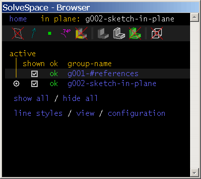
To navigate to a group’s page, click that group’s name (e.g., “g002-sketch-in-plane”). The links may also trigger actions in the sketch. For example, in the above screenshot, all of the groups are shown. To hide a group, click the box in the “shown” column.
As a convenience, the text window will sometimes automatically navigate to a page that is likely to be relevant. For example, when a new group is created, the text window displays that new group’s page. It’s always possible to navigate to a different page, by clicking the “home” link at the top left corner (or pressing Esc), and following the links from there.
When sketch entities are selected (e.g., the user has clicked on them with the mouse), information about those entities is displayed in the text window. If a single entity is selected, then information about that entity is displayed. For example, the window display’s a circle’s center and radius.
If multiple entities are selected, then the text window can sometimes display information about all of them. These cases include:
- two points: the distance between the points
- a point and a plane face: the distance from the point to the plane
- two points, and a vector: the distance between the points, projected along the vector
- two plane faces: the angle between the plane faces
Show/Hide Entities
As the sketch becomes more complex, it may be useful to hide unnecessary information. SolveSpace provides several different ways to do this.
Along the top of the text window, a row of icons appears. These icons make it possible to hide and show different elements in the sketch:
workplanes from inactive groups
When a new “Sketch In New Workplane” group is created, an associated workplane is created automatically. These workplanes are either visible whenever that group is visible (item shown), or visible only when that group is both visible and active (item hidden).
- normals
- By default, normals are drawn as blue-grey arrows, in the direction of the normal. These normals may be hovered and selected with the mouse, for example in order to constrain them. This icon may be used to hide them.
- points
- By default, points are drawn as green squares. These points may be hovered and selected with the mouse, for example in order to constrain them. This icon may be used to hide them. If points are hidden, then they will still appear when the mouse hovers over them, and may still be selected.
- constraints and dimensions
- When a constraint is created, a graphical representation of that constraint is displayed in purple. The constraints in a group are visible only when that group is active. To hide them even then, use this icon.
- faces selectable with the mouse
Some surfaces on the 3d model may be selected. For example, the user can select a plane face of the part, and constrain a point to lie on that plane. If faces are shown, then the faces will appear highlighted when the mouse hovers over them. The user can click the mouse to select the face, as they would for any other entity.
As a convenience, faces are automatically hidden when a new sketch group is created, and automatically shown when a new extrusion is created. If this behavior is not what’s desired, then the faces can be shown or hidden manually with this icon.
- shaded view of solid model
The 3D part is displayed as an opaque solid, with lighting effects to give the impression of depth.
This icon is used toggle that effect on or off.
- edges of solid model
Lines are drawn wherever two different surfaces of the solid model meet. If edges are shown but shaded is hidden, then a wireframe display results. The display of meshes may be noticeably slower when edges are shown. The display of NURBS surfaces will not be noticeably slower when edges are shown.
The color of the edges may be set in the line styles.
- triangle mesh of solid model
Use this icon to show the triangles on the model.
The 3d model of the part consists of many triangles; for example, a rectangular face is represented by two triangles.
This is a good way to see how fine or coarse the mesh is before exporting it.
- hidden lines
With the part in a given orientation, some of the lines in the part will be invisible, because they are buried inside the solid part. To show those lines anyways, as if the part were transparent, use this icon. This is useful when drawing a sketch that lies within the volume of the part.
In addition to the above options, it is possible to hide and show entire groups. If a group is hidden, then all of the entities (line segments, circles, arcs, points, etc.) from that group are hidden. The solid model is not affected; if a hidden group contains a circle that is extruded to form a cylinder, then the cylinder will remain visible.
To hide a group, go to the home screen in the text window, by pressing
Escor choosing the link at the top left. A list of groups is displayed, along with their visibility. If a group is visible, then the checkbox in the “shown” column is checked. Click the checkbox; it now appears unchecked, and the group is hidden. The show/hide status of groups is saved in the part file. If a part is imported into an assembly, then entities that were visible in the part file will be visible in the assembly, and entities that were hidden will be hidden.
Active Workplane
SolveSpace represents all geometry in 3d; it’s possible to draw line segments anywhere, not just in some plane.
This freedom is not always useful, so SolveSpace also makes it possible to draw in a plane. If a workplane is active, then all entities that are drawn will be forced to lie that plane. The active workplane (“in plane:”) is indicated in the top line of the text window, at the right.
When SolveSpace starts with a new empty file, a workplane parallel to the XY plane is active. To deactivate the workplane, and draw in 3d, choose Sketch → Anywhere In 3d.
To activate a workplane, select it, and then choose . When a workplane is activated, the view is aligned onto that workplane. The workplane remains active until the user chooses , or a different workplane is activated. If the user rotates the view, so that the view is no longer aligned onto the workplane, then the workplane remains active.
In a Sketch in New Workplane group, the group’s associated workplane may be activated by choosing ; there is no need to select it first.
Active Group
When a new line, circle, or other curve is created, it will be created in the active group. Geometry from the active group is drawn in white; geometry from earlier groups is drawn in brown. Later groups are hidden.
In the text window’s home screen (press Escape, or choose the link in the top left corner), the active group’s line in the list of groups has a selected radio button in the “active” column. All other groups (except g001-#references, which cannot be activated) have an unselected radio button in that column. To activate an inactive group, click its radio button.